I had some issues with my flow visualization which is how I wanted to test the objects in the wind tunnel. I intended to use dry ice with warm water to give off the smokey effect of CO2, but it did not work as well as I thought it would. I could not record a video of it because it was basically invisible unless you were there in person. I might try other methods of smoke like smoke bombs or something, but this is my situation right now. I really put my money on the dry ice after reading many reviews on how good the smokey effect is. I might try it again with more in a darker place with better lighting so that I can get a good video of us testing a toy helicopter in the wind tunnel.
Thursday, April 27, 2017
Monday, April 24, 2017
Flow Straightener
A flow straightener, sometimes called a honeycomb, is a device used to straighten the air flow in a wind tunnel. It is a passage of ducts, laid along the axis of main air stream to minimize the lateral velocity components caused by swirling motion in the air flow during entry. The cross-section shapes of these "honeycombs" may be of square, circular and regular hexagonal cells.


Wednesday, April 19, 2017
Open Circuit Wind Tunnels
The advantages of open circuit wind tunnels is first the low construction cost. These are easy to make and are cheap. It's a better design for propulsion and smoke visualization. There is no accumulation of exhaust products in an open tunnel.
The disadvantages are poor flow quality in the wind tunnel. The tunnels should also be kept away from other objects in the room that produce asymmetries to the bellmouth. It can also be affected by wind and weather.The fan must must continually accelerate flow through the tunnel. It is also noisy which can be inconvenient.
The disadvantages are poor flow quality in the wind tunnel. The tunnels should also be kept away from other objects in the room that produce asymmetries to the bellmouth. It can also be affected by wind and weather.The fan must must continually accelerate flow through the tunnel. It is also noisy which can be inconvenient.
Monday, April 17, 2017
Closed Circuit Wind Tunnels
The advantages of closed circuit wind tunnels are that the fan blades are less vulnerable to damage. The noise is lower and the particle being tested can be easily contained. Outside air movements like air vents don't affect the wind tunnel. The power requirement for a given speed is lower. The air entering the test section is also free of debris.
The disadvantages are that the cost for these types of wind tunnels are significantly higher compared to the open circuit wind tunnels. The recycled air supply can be disastrous when working with combustion engines. It requires more space as these tend to be a bit bigger. The increeasing air pressure can be an issue during prolonged use.
The disadvantages are that the cost for these types of wind tunnels are significantly higher compared to the open circuit wind tunnels. The recycled air supply can be disastrous when working with combustion engines. It requires more space as these tend to be a bit bigger. The increeasing air pressure can be an issue during prolonged use.
Wednesday, April 12, 2017
Schlieren photograph

Now if the parallel rays of light encounter a density gradient in the test section, the light is bent, or refracted. In our schematic, a shock wave has been generated by a model placed in the supersonic flow through the tunnel test section. Shock waves are thin regions of high gradients in pressure, temperature and density. A ray of light passing through the shock wave is bent as shown by the dashed line in the figure. This ray of light does not pass through the focal point, but is stopped by the knife edge. The resulting image recorded by the camera has darkened lines that occur where the density gradients are present. The model completely blocks the passing of the light rays, so we see a black image of the model. But more important, the shock waves generated by the model are now seen as darkened lines on the image. We have a way to visualize shock waves.
Monday, April 10, 2017
Smoke Section
This blog post is regarding to problems that I encountered while doing the smoke section. I cut out two holes in the jar for the pipes. One hole was for the pump for me to manually pump the dry ice CO2 into the wind tunnel. The other hole was for the pipe to enter the wind tunnel.
The second hole was a little to big making it harder for me to close it with hot glue as hot glue is a water tight sealant. I had to redo the whole thing which took an extra day, but that's engineering for you. I also had to change the positions of the pipes to make it easier for the CO2 to hit the object being tested in a uniform way.
The second hole was a little to big making it harder for me to close it with hot glue as hot glue is a water tight sealant. I had to redo the whole thing which took an extra day, but that's engineering for you. I also had to change the positions of the pipes to make it easier for the CO2 to hit the object being tested in a uniform way.
Friday, April 7, 2017
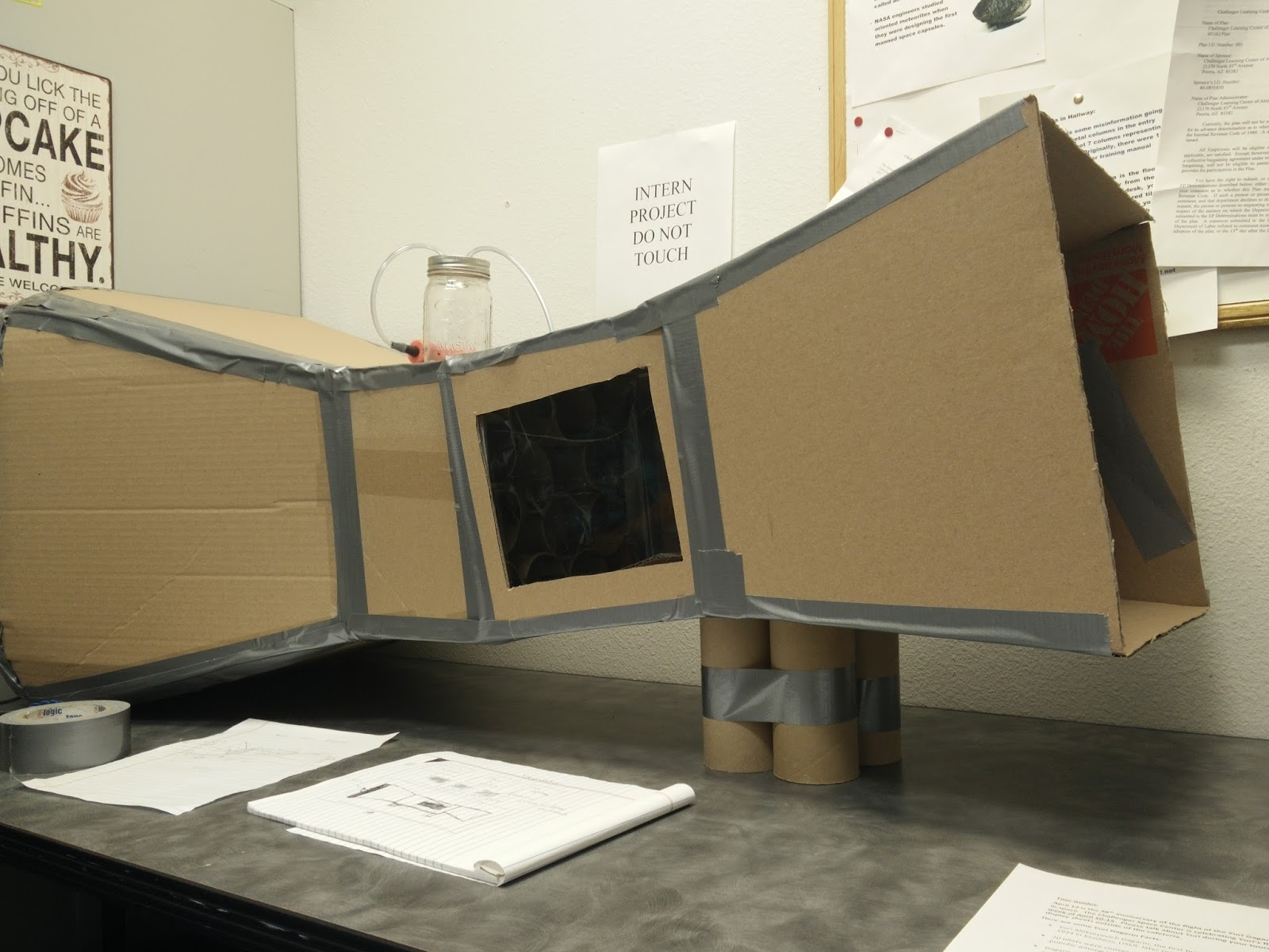
Final Product
04/07/17
I have finally finished my wind tunnel. The last few weeks here at my internship, I will be making some test models for the wind tunnel and I will also be working on my display for the center that incorporates the wind tunnel. My on-site adviser will get dry ice one day where we will take a video of us testing the wind tunnel with the models I created.

I have finally finished my wind tunnel. The last few weeks here at my internship, I will be making some test models for the wind tunnel and I will also be working on my display for the center that incorporates the wind tunnel. My on-site adviser will get dry ice one day where we will take a video of us testing the wind tunnel with the models I created.
Tuesday, April 4, 2017
The World's Largest Wind Tunnel
04/04/17
The largest wind tunnel in the world is big enough to test a 737 airplane, and is part of NASA Ames Research Center’s state-of-the-art aerodynamics complex.
The wind tunnel, which is 80 feet by 120 feet, is actually one of two giant wind tunnels at NASA Ames National Full-Scale Aerodynamics Complex at Moffett Field. As it’s able to accommodate planes with wing spans of up to 100 feet, nearly all commercial aircraft made in the United States since 1987 have been tested in the subsonic tunnel. The tunnel can replicate the wind conditions of flight via six 22,500-horsepower motors with blades as tall as four-story buildings. It’s also used to test flight technology for space, such as parachutes for Mars missions.

Subscribe to:
Posts (Atom)